How to Time Video Cameras, Recorders & Other Sources
Video timing refers to the process of aligning the technical parameters of video sources such as cameras, tape recorders and hard disk recorders so they are "in sync" with each other. The standard method of timing requires some sort of technical monitoring device such as the waveform monitor pictured below.

Waveform Monitor/Vectorscope (left) and Video Monitor (showing colour bars)
If you are working in an environment which uses multiple video sources, it is very important that they are correctly synchronised ("timed"). If the timing is out you will experience problems such as picture disturbances or distorted colours when you cut between different sources.
The way you time your sources will vary depending on the type of equipment you use.
- Amateur and semi-professional equipment often doesn't need to be timed at all. This is because the timing is done automatically without the operator even being aware of it. This level of production also has less demanding specifications than broadcast-level production.
- At the professional level, timing is much more laborious. Older analogue equipment is generally timed manually, using controls on the equipment and a waveform monitor/vectorscope for reference. Newer digital equipment is more automated but some manual timing (or at least checking) is usually required.
NOTE: If you're looking for detailed, step-by-step instructions for your equipment, you'll need to consult your operating manuals and/or technical director. Every steup is different and we can't give you any instructions specific to yours. The instructions below are only a general guide to the steps you'll probably need to take.
The Timing Procedure
Establish the Video Reference

First of all you need a video reference point. This is a video source that will be used as the benchmark - all other sources will be timed to this, i.e. You will adjust the parameters of each source until they are the same as the reference.
The best video reference is a colour bar pattern, usually generated by a specialist piece of equipment like a Synch Pulse Generator. This is a very precise, reliable generator of reference signals. An example of a colour bar signal is shown on the right but there are many variations available.
Establish Each Vision Source

Professional video cameras, recorders and other equipment have the ability to output a test pattern of colour bars, like the one pictured right. There is usually a switch on the camera itself, or this control could be done by the CCU (Camera Control Unit).
It is very important to know exactly what sort of bars the source is outputting. There are different "levels" of bars and each type needs to be interpreted differently. The main consideration is the percentage. Most bars are either 75% bars or 100% bars. Make sure your monitor is calibrated to read the same type of bars you are using.
Black Level
Also known as the setup or pedestal, this sets the video level of the darkest parts of the picture, i.e. black. Set the waveform monitor to magnify the waveform, then adjust the black level until you see a defined line just above the 300mV line.
If the black level is too low the picture will be "crushed" - all dark areas of the picture are merged together as black. If the black level is too high the picture will lack contrast and appear washed out.
Video Level
This measures the overall level of the video output in volts (or millivolts). The standard required level is 1 Volt. Adjust the video level until the white bar sits just on the 1V mark on the waveform monitor.
Too much video level will cause the picture to appear over-exposed and create nasty effects. Too little video level will cause the picture to be dark and lacking contrast.
Chroma Level
The chroma (colour) level is separate from the video level and must be adjusted independently. Adjust the chroma level until the bottom of the green bar sits just below the 300mV line on the waveform monitor.
Too much chroma will make the picture over-saturated, with intense gaudy colours. Too little chroma level will make the picture under-saturated, lacking colour and vitality.
Horizontal Phase
Also known as the synch pulse, the horizontal phase adjustment is what controls the picture's horizontal position.
If the synch pulse is out of phase, the picture will move sideways when cutting between different sources.
Subcarrier Phase
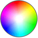
Related to chroma phase, the subcarrier phase controls the appearance of colours. Try to visualise of all the colours in the picture as being part of a 360° circle, and each video source having its own unique colour wheel which it uses as a reference for all its colours.
When you adjust the subcarrier phase you are effectively "rotating" this wheel a certain number of degrees. Each source must be rotated until it is in phase with the reference signal. When you cut between the reference and the source, the vectorscope display should be the same.
If the subcarrier phase is out, the colours will be wrong when you cut between sources. For example, one camera might look fine but the next camera shows people's faces to be purple.
Example
This example is a document from New Zealand's Trackside Channel, a racing and sports television channel specialising in outside broadcasts. This guide details the channel's standard operating procedure for timing video cameras and VT machines.
Trackside Video Timing Guide (PDF, 110KB)
See also: